Table of Contents

IH: Electrical System
SWITCHES
Keyswitch
Subdocuments
The Keyswitch is fed from the main Circuit Breaker. Typically, this feed wire is RED. The Keyswitch has two positions (besides OFF).
There is a RUN position & a LIGHTS position. This allows the lights to be off for starting (especially kick starting) but then can be turned on by moving the keyswitch to the second on position. But sometime in the late 70's, the MoCo began putting a shorting wire across both output connections of the Keyswitch. This meant that all the circuits are powered whenever the Keyswitch is ON, so that the lights are guaranteed to be on (basically making the keyswitch simply an ON/OFF switch). The Keyswitch labels were likely to be B - IG - L for Battery, Ignition & Lights.
Brake Switch
 |
|||||||
|---|---|---|---|---|---|---|---|
| Front and Rear Brake Switches | |||||||
| Year Model | Position | Switch Part# | Additional | Year Model | Position | Switch Part# | Additional |
| 1959-1966 | Rear | 72004-52 | Complete | 1973-1981 | Front | 72001-69B | Switch only |
| 1967-1972 | Rear | 72004-67 | Kit with wires | 1977-1978 | Rear | ||
| L1969-1972 | Front | 71900-70 | Includes terminal | 1979-1985 | Rear | 72023-51A | Switch only |
| 1973-1974 | Rear | 72004-70 | Switch only | 1982-1985 | Front | 71574-82 | Includes terminal and wiring |
| 1975-1976 | Rear | 72004-75 | Switch only | ||||
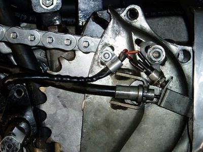
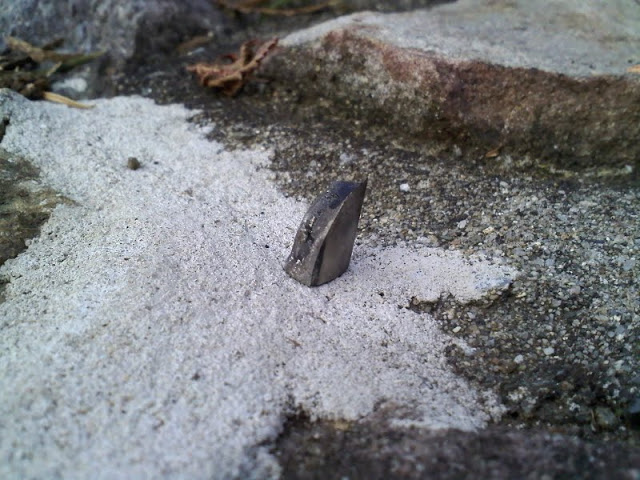
The stock 77 rear brake light switch is a cheesy little thing that attaches to the pressed metal inner sprocket cover/brake cable mounting plate under the aluminum sprocket cover. 1) They are tiny and often get clogged up with chain gunk in there. The little flat plate sticking out from the end of the cable operates it. It mounts on a right angle metal bracket going to the quarter nut and stud above, allowing adjusment.
Rear Brake Switch (72001-69B) on 1977 XLCH.
 2)
2)
INSTRUMENTS
Sub Documents
Speedometers
All Ironhead Sportster speedos, whether tranny driven or front wheel driven, are 2:1 ratio.
1957-72 - Transmission Driven - 2:1 Ratio Speedometers
1973-83 - 19“ Wheel Driven Right Side - 2:1 Ratio Speedometers 3)
1984-85 - 19” Wheel Driven Left Side - 2:1 Ratio Speedometers
. Driven Unit = 67127-84A for use with 2:1 Speedometers - (CableRPM-2000=60mphOnSpeedo)
|
|||||
|---|---|---|---|---|---|
| MPH Speedometers | KPH Speedometers | ||||
| Part# | Year Model | Notes | Part# | Year Model | Notes |
| 67007-52 | 1952-1954 K Models | 120 MPH | 67008-52 | 1952-1956 K Models 1957-1958 Sportsters (except XLC/XLCH) | KPH |
| 67007-54 6007-54A | 1955-1956 KH 1957-1958 Sportster (except XLC/XLCH) | 120 MPH | 67008-52 | 1952-1956 K Models 1957-1958 Sportsters (except XLC/XLCH) | KPH |
| 67007-59 | 1959-1964 Sportsters | 120 MPH | 67008-59 | 1959-1967 Sportsters (except XLCH initially) | KPH |
| 67007-59A | 1965-E1967 Sportsters | 120 MPH | 67008-59A | 1959-1968 Sportsters | KPH. New part# in 1968 retrofit |
| 67007-59B | L1967-E1969 Sportsters | 150 MPH | 67008-59B | 1959-1969 Sportsters | KPH |
| 67007-59C | L1969 Sportsters | 150 MPH | 67008-70 | 1970 Sportsters | KPH |
| 67007-70 | 1970 Sportsters | 150 MPH | 67021-70 | 1970-1972 Sportsters | KPH |
| 67020-70 | 1970-1972 Sportsters | 150 MPH | 67021-73 | 1973 Sportsters | KPH |
| 67020-73 | 1973 Sportsters | 150 MPH | 67021-73A | 1973 Sportsters | KPH update in 1976 |
| 67020-74 | 1974 Sportsters | 150 MPH | 67043-74 | 1974 Sportsters | KPH |
| 67020-74A | 1975-1976 Sportsters | 150 MPH update retros to 1974 | 67043-74A | 1975-1976 Sportsters | KPH update retros to 1974 |
| 67020-74B | 1977-1979 Sportsters | 150 MPH update retros to 1974 | 67043-74B | 1977-1979 Sportsters | KPH update retros to 1974 |
| 67007-79 | 1979 XLS | 120 MPH | 67043-75B | 1980-1981 XL 1981 XLS | KPH |
| 67007-79A | 1980 XLS | 120 MPH, w/ bracket replaced 67007-79 in 1980 | 67043-75C | 1982-1983 XL 1982 XLS | KPH supercedes 67043-75B |
| 67020-75D | 1980-1983 XL 1981-1982 XLS | 85 MPH | 67008-79 | 1979 XLS | KPH, w/ bracket |
| 67016-83 | 1983 XLS 1983-1984 XLX | 85 MPH, complete | 67008-79A | 1980 XLS | KPH |
| 67037-83 | E1984 XL | 85 MPH, w/ wiring | 67010-83 | 1983 XLS 1983-1985 XLX | KPH, complete |
| 67061-83 | 1984 XLS | MPH, w/wiring | 67062-83 | L1983-1985 XLX 1984-1985 XLS | KPH, w/wiring |
| 67100-83 | 1983-1984 XLS | MPH, complete | 67101-83 | 1983-1985 XLS | KPH, complete |
| 67016-85 | 1985 XLX | MPH, complete | |||
| 67037-85 | 1985 XL | MPH, w/ wiring | |||
| 67061-85 | 1985 XLS/XLX | MPH, w/wiring | |||
| 67100-85 | 1985 XLS | MPH, complete | |||
| 67037-85A | L1984-1985 XL 1985 XLS/XLX | 120 MPH, w/ wiring | |||
Speedometer Drive Gear (1952-1972)
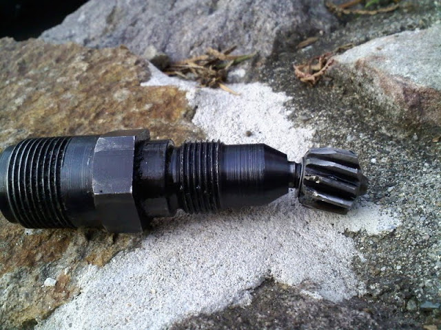
The mechanical speedometer on K Models / XLH from 1952-1972 and XLCH from 1959-1972 is run by a (11T) gear unit attached to the transmission. It is driven by the countershaft low gear. The drive is a round insert through the transmission casing with a beveled rotating gear on the end that meshes with the low gear. A cable is attached which of course goes to the speedometer. The speedo drive gear rotates the inner part of the cable which rotates the mechanism in the speedo head to operate the odometer and speedometer. 4)
This was not used on 1958 XLC or XLCH.
 5)
5)  6)
6)
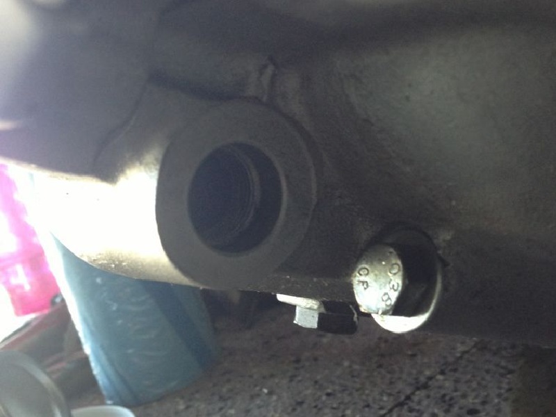
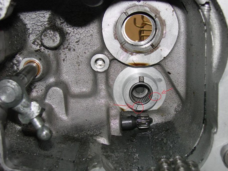
The speedometer drive unit goes into the hole in the lower right side of the transmission beside the oil pump.
The pic on the right shows the drive unit as installed from the inside.
 7)
7)  8)
8)  9)
9)
Staring down a problem with the speedometer not working can be catastrophic when visualizing the possible causes and particularly the effects thereof.
Also, if you're not going to use the OEM speedo drive, then remove it and plug the hole. That freewheeling drive has been known to destroy the trans and engine case. 10)
Just unscrew it and screw in a plug. Colony makes a Speedometer Drive Block-Off Plug (2057-2) for K Models and XLs.

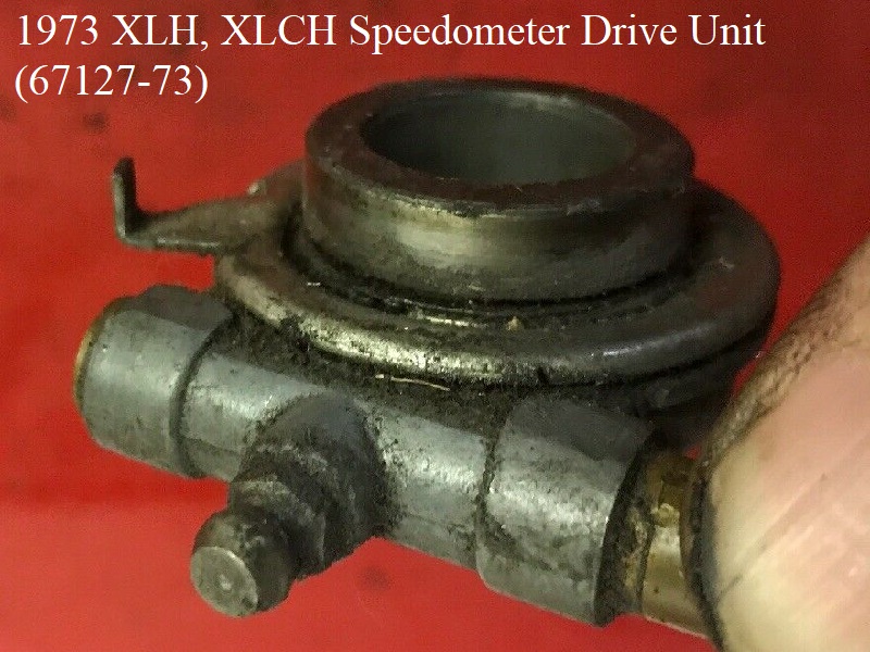
Speedometer Drive Gear (1973-1983)
The speedometer drive unit was moved to the front wheel, right side, in 1973. 1970-1973 XLH, XLCH used Veglia (Italian made) instruments. And the 73 drive unit (67127-73) was also from Veglia. In 1974, the MoCo started using Nippon Seiki (Japan) gauges and drive units. The new drive unit didn't have the grease fitting as did the 73 unit but has the same part number as in 73, and retrofitting to 73 models for replacement. The unit has a .300“ wide seal spacer.
Common Issues:
The unit fits on the axle, somewhat like a spacer, with a small tang that fits into the hub to keep the outer assembly from spinning. If the tab doesn't seat into the hole in the hub correctly, it can come loose and scrape against the hub as it turns and stop the speedometer from working.
The front wheel speedo drive unit contains two small meshed gears and some grease. The gears can come loose or receive wear. The grease can get sand etc in it, etc etc. This wil also affect the accuracy of the speedometer. Easiest way to fix that is to just replace the unit. You could try to make it work by removing and refurbishing it but they do not really come apart without wrecking it. 14)
There is also an internal threaded stub on the drive unit for the speedometer cable to screw into. The cable end has a male threaded nipple made to it that screws into the female threads on the drive unit stub. The threaded stub should not wiggle or have any slack that would allow the cable to wiggle at this connection or it will alter the speedometer readings.
The drive unit is not considered servicable and it should get periodically lubed when you lube the speedometer cable. However, if you rarely lube that cable, the drive unit doesn't get lubed either. There is a little wire clip ring that holds the rotating cover with the finger snuggly to the body of the unit but the cover won't come all the way off. However, there is enough room gained with the clip removed to repack the unit with grease. You can clean the unit out with brake cleaner, blow it out with compressed air and drop a couple drops of some lube (75-140 transmission fluid?) in it. Spin it around a couple times to distribute the oil, repacked it with wheel bearing grease and reassembled it with a new outer gasket. 15)
You have to remove the axle to replace the drive unit since the axle slides thru the forks/wheel from the right.


Speedometer Cables
If you're planning to use a post 1970 speedometer head on a pre 1970 bike; 19)
Use the -70 cable if you're using the Veglia head and a transmission mounted speedometer drive unit.
Use the -73 cable if you're using the Veglia head and a disc brake front wheel speedometer drive unit.
You'll need to make a custom cable if you are using a Nippon Seiki speedometer head.
Speedometer Hole Plug (1958-1972 XLCH)
There is a 11/16”x20 hex head hole plug (24575-52) for 1958-1972 XLCH's not running a speedometer.
It gets installed in place of the speedometer drive gear unit in the lower rear of the right case.
 20)
20)
Deleting Wheel Mount Speedometer Drive Unit (1973-Up)
You'll have to remove the drive unit and replace it with a spacer to keep the integrity of the assembly.
There is no down side of removing the drive other than losing the drive cable to the speedometer (as long as you use an equal length spacer in it's place).
The bearing “end play” is set by the Hub Spacer length (and the thickness of the shims, if used). The speedo drive unit (on the axle) can be removed as long as you replace it with a spacer of the same width as the drive unit. In some cases, there are spacers inside the oil seals, just wide enough to make it outside the seal, and then another spacer (external bearing spacer) outside the seal sets the positioning of the wheel (relative to the fork leg). In other cases, like the speedo drive unit, it may include both the external spacer for positioning and the internal (inside the oil seal) spacer in the one unit. 21)
In the end, you have (from the head side of the axle):
The oil seal spacer,
The inner bearing race,
The hub spacer,
The other inner bearing race,
The other oil seal spacer
And finally, the external bearing spacer (that sets the position of the rotor in the caliper and should make the tire centered between the forks).
This sandwich of parts are all clamped together by the axle. None of those parts rotate.
The wheel rotates because the outer bearing race (fitted into the wheel hub cavity) rotates around the stationary inner bearing race.
As long as you use an external bearing spacer of equivalent width (length) to the speedo drive unit, the rotor and tire should maintain their positioning.
Spacer Alternatives to replace the now removed drive unit:
You can cut the outer race off of old wheel bearings and use just the inner race as spacer. It can be trimmed shorter if needed, or add washers to the outside for more length. But they are the perfect size to mate with the inner race of the week bearing and are the right inside diameter to fit the axle. 22)
Or you can buy spacers made for this job.
These are dims from VulcanWorks for the spacers they sell for just this reason. They call them Speedometer Drive Eliminator Spacers.
If you have the OEM part number of your drive unit, they list it along with the dimensions and they are cheap enough. Made from 1214 alloy steel & satin chrome plated, 1-1/8“ OD by 3/4” ID. These are made for 3/4“ Timken bearing wheels, with a hard coat finish so they can be used as wheel seal adapters.
Here is the link to their site: https://secure.vulcanworks.net/store/speedometer-drive-eliminator-spacers-speedo-harley.html
Here are the dims from their site along with part numbers. All of these are not made for Sportsters. But if you do a search for the part number of the drive unit… to buy one… you may get several different dims from several different companies for the same part number drive unit. Maybe the dims below will help some.
|
||
|---|---|---|
| Spacer Length | Drive Unit Spacer Replaces | Notes |
| 0.531” | 67073-81 | 1981-1984 FL, 1982-1986 FLT / FLHT. Right side drive has no seal spacer. |
| 0.93“ | 67127-84, 67127-84A | 1984-1995 FXR, 1984-1994 Sportster. Left side drive has .350” wide seal spacer |
| 0.94“ | 67132-85A | 1987-95 FXLR. Left side drive has .321” wide seal spacer. Drive is for a 2240:60 ratio |
| 0.79“ | 67127-73 | 1973-E1984 FX / FXR (Except 1980 FXWG & FX), 1973-1983 XL / XLH, 1979-1983 XLS / XLX. Right side drive has .300” wide seal spacer ( .268“ per V-Twin). Drive unit is for a 2:1 ratio. |
| 1.248” | 67101-96 | 1996-1999 FLHT / FLHR. Left side drive has .442“ wide seal spacer. Drive unit is for a 2240:60 ratio. |
| 1.28” | 67166-88, 67073-87A | 1987-1995 FLT / FLHT / FLHTC / FLHTCUI / FLTCU and 1996 FLTCUI Left side drive has .440“ wide seal spacer. Drive unit is for a 2240:60 ratio. |
| 1.41” | 67120-84B | 1984-1995 FXWG / FXST / FXDWG w/ 21“ wheel. Left side drive has .574” wide seal spacer. Drive unit is for a 2240:60 ratio. |
| 1.49“ (Vulcan) 1.426” (V-Twin) | 67125-86A | 1986-1995 FLSTN, FLSTC / FLSTF w/ 16“ wheel. Left side drive has .608” wide seal spacer. Drive unit is for a 2240:60 ratio. |
| 67124-80 | 1980 FX w/ 19“ wheel (except FXWG). Right side drive has .250” wide seal spacer. kilometers per hour only (does not work for MPH 23) |
|
Tachometers
The first mention of a tach used on a Sportster is the L1962 XLCH per the -63 parts catalog.
Several tach kits were sold in 1965 for current and prior model XLH models per the -66 parts catalog supplement.
|
||
|---|---|---|
| Year Model | Tach | Notes |
| L1962- XLCH | 92051-62 | Part of Tach Kit (92050-62) mounted on handlebars. (Smith) |
| 1962-1964 XLCH | 92051-65 | Part of Tach Conversion Kit (92050-62A), replaces (92051-62) |
| 1965-1966 XLCH | 92051-65 | Part of Tach Kit (92058-59) mounts speedometer and tach to forks on 1959-1965 XLCH |
| 1967-1969 XLCH | 92051-65 | Part of Tach Kit (92057-67) |
| 1957-1964 XLH | 92051-65 | Part of retro Tach Kit (92049-57) in 1963 |
| E1965 XLH | 92051-62 | Part of Tach Kit (92049-65) |
| 92051-62A | Replaced 92051-62 with Tach Kit (92050-62A) | |
| L1965-1966 XLH | 92051-65 | Part of Tach Kit (92049-65A) |
| 1967-1969 XLH | 92051-65 | Part of Tach Kit (92048-67) |
| 1970 XLH/XLCH | 92059-70 | Part of Tach Kit (92048-70). Made by Veglia (Italy) |
| 1971-1973 XLH/XLCH | 92051-70 | Part of Tach Kit (92048-71) Made by Veglia (Italy) |
| 1974 XLH/XLCH | 92051-74 | Made by Nippon Seiki (Japan) |
| 1975-1976 XLH/XLCH | 92051-74A | Retro to 1974. Made by Nippon Seiki (Japan) |
| 1977-1979 XLH/XLCH | 92051-74B | Retro to 1974. Replaced by 92051-75D. Made by Nippon Seiki (Japan) |
| 1979 XLS | 92053-79 | With bracket. Replaced by 92053-79A. Made by Nippon Seiki (Japan) |
| 1980 XL | 92051-75D | With bracket. Made by Nippon Seiki (Japan) |
| 1980 XLS | 92053-79A | With bracket. Supersedes 92053-79. Made by Nippon Seiki (Japan) |
| 1981-1982 XL/XLS | 92051-81 | Electronic. Replaced by 92051-81A. Made by Nippon Seiki (Japan) |
| 1983 XL | 92051-81A | Electronic. Replaced 92051-81. Made by Nippon Seiki (Japan) |
| 1983-1984 XLS | 92060-83 | Electronic, complete w/ bracket |
| 1983 XLS | 92059-83 | Electronic, w / bulb and socket |
| 1983 XLS | 92060-83 | Electronic, complete |
| E1984 XL | 67111-83 | Speedometer and Elect Tach Kit (67099-84) |
| L1984-1985 XL | 67111-85 | Speedometer and Elect Tach Kit (67099-85) |
| 1985 XLS | 92059-85 | Electronic, w / bulb and socket |
| 1985 XLS | 92060-85 | Electronic, complete w/ bracket |
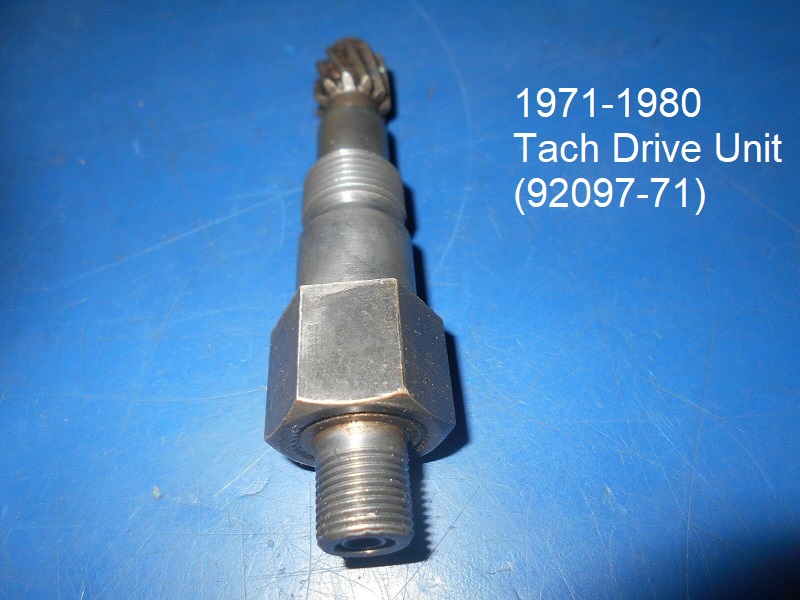
Tach Drive Gear (1971-1980)
The tach drive gear unit (92097-71) for 71-80 models screws into the cam cover between #3 and #4 cams.
A worm type gear is pressed onto #4 cam that drives the tach drive gear unit. Both gears on the cam and tach drive have 11 teeth.
So there is a 1:1 ratio between these two gears.
However, the cam turns 1 revolution per every 2 TDC revolutions of the front piston leaving a 2:1 ratio at the tachometer head.
The drive unit gets a washer gasket (67142-52) on top for the threaded coupler on the cable connecting the drive unit to the tach head.


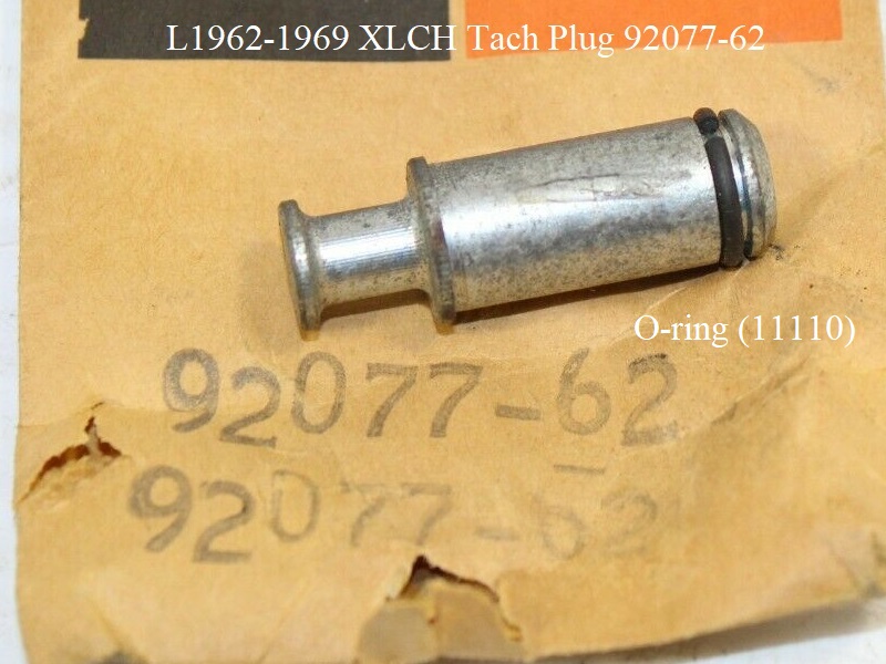
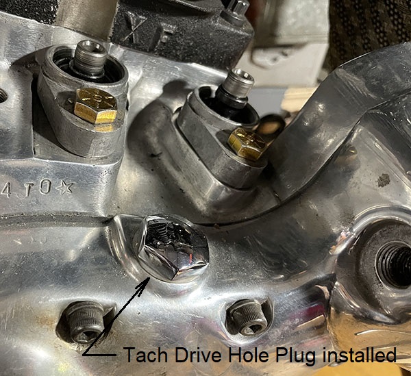
Tach Hole Plug
If you are not using the tach, you can remove the drive unit and plug the hole.
L1962-1969 XLCH tach plug (92077-62) is used to plug the hole at the magneto.
The plug is pushed into the hole and it has an O-ring (11110) on the end.


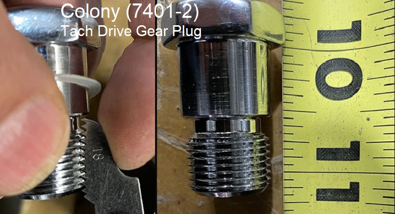
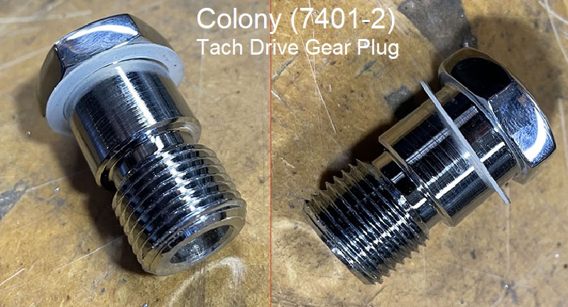
1971-E1984 Sportsters can use the Colony plug below to plug the hole in the cam cover.
Just unscrew the drive and screw in the plug (with seal washer).
 29)
29)  30)
30)
Misc Gauges
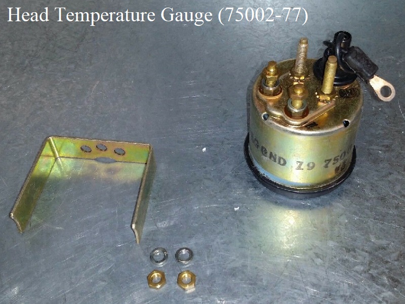
HD Head Temperature Gauges
Head Temp Gauge (75002-69) became available through the -70 Sportster parts catalog (among other models) as part of Kit# (75000-69) and also sold by itself.
Made for +12V systems from 1965-1976.
The gauge signal comes from a sending unit (75005-69) attached to the front head with a thin nut (7692) and wired with a cable assembly (75003-69).
The gauge sits inside a handlebar mounted bullet style housing (74479-68) with a bezel (74472-68).
The assembly mounts to the handlebar with mounting bracket (74484-68) and handlebar clamp (45030-65A).
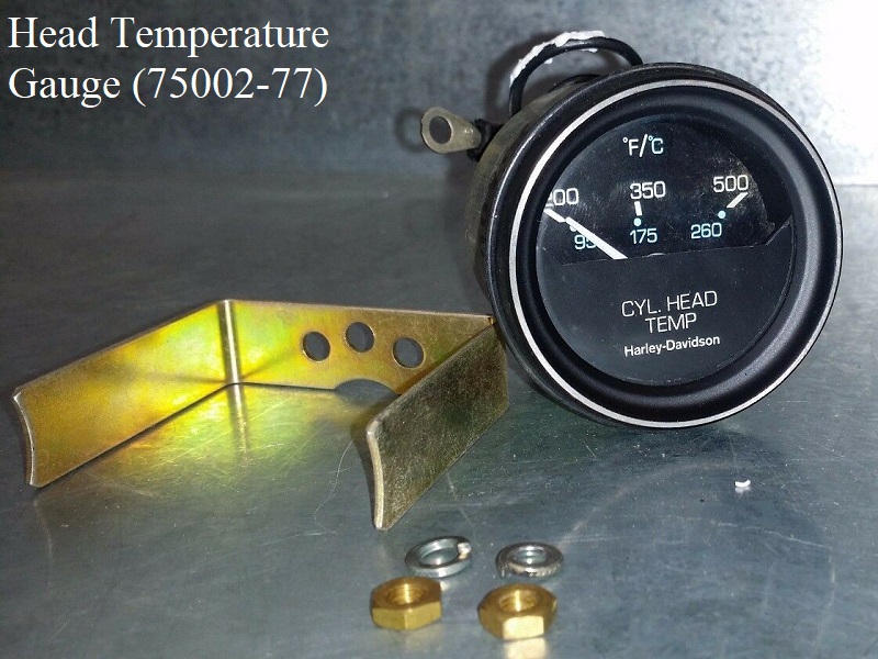
Head Temp Gauge (75002-77) was for use on 1977-1981 Sportsters. It has an illuminated face and measures temps 200-500F (95-260C).
Per IronMick, to install the sending unit for the gauge, you drill a hole in the top fin of the front cylinder head (left side). 33)
Then insert the threaded part of the sender into the hole. The special nut is thin enough to fit between the two fins.
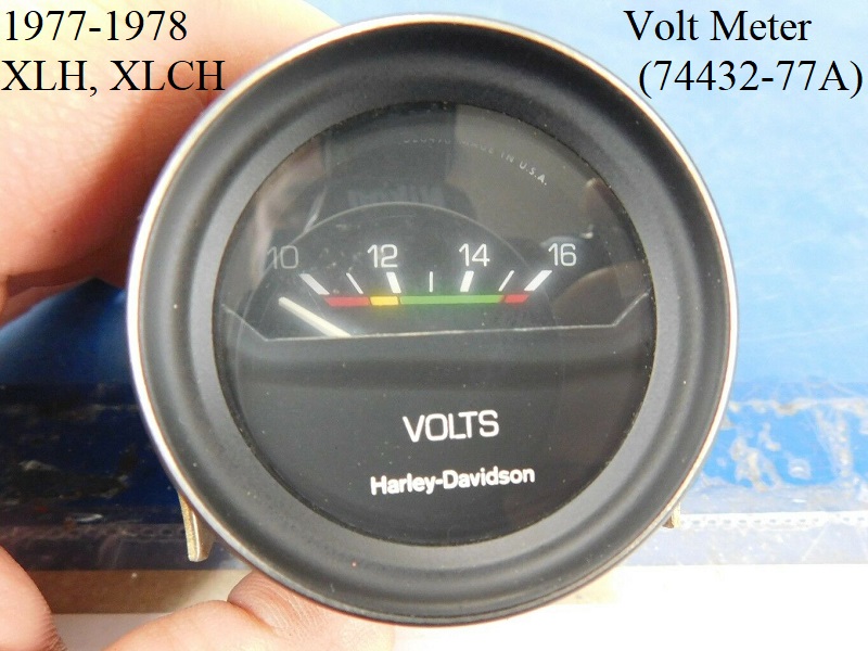
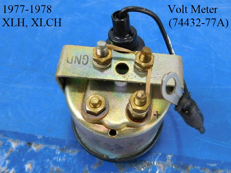
Volt Meter
1977-1978 XLH, XLCH got a volt meter (74432-77). The part number was updated in the -78B parts catalog to (74432-77A).
It has a black face, is app. 2“ in diameter, 2.3” wide bezel, 2“ long and reads +10 to +16 volts.

LIGHTS
Headlight
In Late 1977, Shorter Headlight Bracket Mounting Bolts Used
- In late 1977, shorter bolts were used to mount the headlight bracket to allow it to be installed or removed with the handlebars clamped in place. The shorter bolt also allows for the mounting of the headlight bracket after mounting the speedometer / tachometer bracket underneath the handlebar upper clamp which provides easy access to the wiring connections at the headlight terminal block.
- The shorter bolts 5/16”x18 1-1/8“ (43868-72) replaced the longer 5/16”x18 1-1/4“ bolts (2871W). The longer bolts can also be shortened for this application. 39)
Tail Light - License Light
Turn Signals
(1973-85 Simple Turn Signal Function)
These model years HD implemented a basic turn signal circuit using a bi-metallic, current/heat-controlled, Turn Signal Flasher Unit similar to those in automobiles. The 12v power wire feeds thru the Flasher and then goes to the handlebar switches. The Left or Right handlebar turn signal switch could be pressed to feed the power to the bulbs on that side of the bike. When connected to the bulbs, thus completing the circuit, the Flasher unit would supply power until the current flowing through it would heat the bi-metallic elements sufficiently to cause a break (like a circuit breaker) in the circuit. Once the flasher cooled down, the bi-metallic elements would again conduct power to the turn signal bulbs, thus causing an on-off cycle that repeated until the handlebar switch was released.
From 1973-1981, the handlebar TS switches were small pushbuttons. They were momentary contact. The turn signal only stayed flashing while the button was depressed.
From 1982-1985, the handlebar TS housings were changed, creating a larger TS button. The switches were still momentary contact, working only while the button was depressed.
- (Converting to LEDs) - Because of the way these bikes were wired, you can replace the single current/heat-activated flasher with a new electronic flasher that is capable of properly flashing LEDs or Incandescent bulbs. However, the indicator light may need to be modified by grounding one side and feeding power from the right and left circuits thru diodes to the power side of the indicator.
Signal-STAT Flashers (6v)
From a service bulletin in 1961:
Different flasher modules have different characteristics. It is important to use the appropriate one when replacing them. For instance:
- Flasher (68543-61) was originally used for directional signals with 21 candlepower to the front and rear lamps (6872-50) and 1 candlepower pilot lamps (71090-47). If any of the signal bulbs burn out, the pilot lamp in the same circuit will remain on.40) Flasher (68543-61A) was the replacement for directional signals. 41)
- Flasher (68542-61) is used for pursuit lamps or other flashing lamps which use either one or two 32 candlepower lamps (68715-49).42)
|
|||||
|---|---|---|---|---|---|
| Year model | Part # | Used For | Markings | Application Voltage | Notes |
| 1957-E1963 | 68543-61 | Directional signals | N 221-6V | 6 | 3-prongs: X (hot), L (switched), P (not used) |
| 1957-1965 | 68543-61A | Directional signals | 143-12V | 6 | Replaced 68543-61 in L1963. Disregard the 12V markings per HD. 2 prongs: X (hot), L (switched) |
| 68542-61 | Pursuit lamps | F 421-6V | 6 | ||
Hazard Warning Flashers
1968 and 1969 XLH got a Flasher Kit (68541-68). 1970-1972 XLH/XLCH got Flasher Kit (68540-70). 1973-1975 XLH/XLCH got Flasher Kit (68540-73).
Hazard Flasher Kit (68540-70)……… Click Here to download the instruction sheet.
 43)
43)  44)
44)  45)
45)
Factory Horns
Subdocuments
1952-1964 K model, Sportster 6V Horns
|
||||||||
|---|---|---|---|---|---|---|---|---|
| 1952-1964 K model, Sportster “Jubilee” 6V Trumpet Horn and Parts | ||||||||
| Year Model | Horn Part# | Horn Type | Horn Mtg. Bracket | Horn Power Pack | Power Pack Mtg. Bracket | Support Bracket | Horn Cover | Horn Screen |
| 1952-1954 K Models (all) | 69003-52 | 69142-52 | (included w/ horn) | 69013-54 laminated rubber | - | 69140-52 69140-52A (59) | 69016-52 | |
| 69019-52 | 69142-52 | 69015-52 | ||||||
| 1957-1964 XL/XLH | 69019-57 | Delco Remy | 69029-57 | 69014-54 | 69013-54 | 69031-57 | 69140-54 | 69016-52 |
| 1959-1961 XLCH | 69002-47B 69002-47C (62) 69002-62 (63) | Delco Remy Model 16 Type M | Included w/ horn. Parts order (69052-62) x (4) laminated). 69122-61P (67) | - | - | 69031-57 | - | - |
| 1962 XLCH | 69002-47C 69002-62 (63) 69002-62A (66) | Delco Remy Model 16 Type S | - | - | 69031-57 | - | - | |
| 1963-1964 XLCH | 69002-62 69002-62A (66) | Delco Remy Model 16 Type S | - | - | 69031-57 | - | - | |
| Horn capacitor (32727-63) added on XLCH engines #63XL-3015-up | ||||||||
1965-1985 Sportster 12V Horns
|
||||||||
|---|---|---|---|---|---|---|---|---|
| 1965-E1973 Sportster 12V Horn and Parts | ||||||||
| Year Model | Horn Part# | Horn Mtg. Bracket | Rubber Isolator Mount | Inner Support Bracket | Horn Cover | Horn Cover Spacer | Horn Ground Strap | Horn Capacitor |
| 1965-1966 XLH/XLCH | 69000-65 (low F note) 69000-76 (76) | 69052-65 69052-65A (66) 69117-65 (67) | 69125-65 5/16”-18 threads | 69129-65 | 69138-65 | 69144-65 | 70016-65 (“U” shaped metal) 70016-65A (braided wire) | 32727-63 on 63-69 XLCH (only) |
| 1967-1972 XLH/XLCH Standard seat | 69000-65 69000-76 (76) | 69117-65 | 69125-65 | 69129-67 | 69138-65 | 69144-65 | 70016-65 70016-65A (68) |
|
| 1970-E1976 XLH/XLCH | 69001-70 (high A note) 69016-76 (76) | 69141-70 | - | |||||
| L1970-E1971 XLH/XLCH w/ Accessory Low Seat | 69000-65 69000-76 (76) | 69117-65 69117-71 (L71) 69117-71A (72) | 62563-65 1/4“-20 threads 69125-65 (L71) 5/16”-18 threads 62563-65 (72) 1/4“-20 threads | 69129-67 69129-71 (L71) 69129-72 (72) 69129-72A (75) 69129-72B (78) | 69138-65 | 69144-65 | 70016-65A | - |
| L1971 XLH/XLCH OEM Low seat | 69000-65 69000-76 (76) | 69117-71 (L71) uses 5/16” iso 69117-71A (72) uses 1/4“ iso | 69125-65 5/16”-18 threads 62563-65 (72) 1/4“-20 threads | 69129-71 69129-72 (72) 69129-72A (75) 69129-72B (78) | 69138-65 | 69144-65 | 70016-65A | - |
| 1972-E1973 XLH/XLCH Low seat | 69000-65 69000-76 (76) | 69117-71A | 62563-65 | 69129-72 69129-72A (75) 69129-72B (78) | 69138-65 | 69144-65 | 70016-65A | - |
|
||||||||
|---|---|---|---|---|---|---|---|---|
| L1973-1985 Sportster 12V Horn and Parts | ||||||||
| Year Model | Horn Part# | Horn Mtg. Bracket | Rubber Isolator Mount | Inner Support Bracket | Horn Cover | Horn Cover Spacer | Horn Ground Strap | Horn Bumper Bracket |
| L1973-E1976 XLH/XLCH | 69000-65 (low F note) 69000-76 (76) | 69117-71A | 62563-65 | 69129-72 69129-72A (75) 69129-72B (78) | 69138-65 | 69144-65 | 70016-65A | bracket 69041-73 bumper (L76-E81) (69042-73) bumper (81- ) (11428) |
| L1976-1985 XLH/XLCH XLS/XLX | 69000-76 (low F note) | 69117-71A | 62563-65 | 69129-72A 69129-72B (78) | XLH/XLCH/XLX XLS (83-85) 69140-76 (chrome assembly) XLS (80-82) 69011-76 (black assembly) | 70016-65A | ||
| Horn assembly 69009-76 includes the cover. Replaced by 69003-76 (78) | ||||||||
| L1976-1978 XLH/XLCH | 69016-76 (high A note) | 69017-76 (assembly) | 70016-65A | |||||
| 1979-later, this horn was only sold in the twin horn kit (69003-76 ) | ||||||||
| 1977 XLCR 1978 XLCR | 69000-76 | 69117-71A | 62563-65 | 69129-72A 69129-72B | 69011-76 (black assembly) | 70016-65A | ||
Twin Horn Kits
The twin horn kits consist of the factory (low note) horn used together with the (high note) horn.
|
||||||||
|---|---|---|---|---|---|---|---|---|
| Sportster 12V Twin Horn Kits and Parts | ||||||||
| Year Model | Horn Part# | Horn Mtg. Bracket | Rubber Mount Bracket | Inner Support Bracket | Horn Cover | Horn Cover Spacer | Horn Ground Strap | Horn Bumper Bracket |
| 69003-70 (70-E76) XLH/XLCH | 69001-70 (high A note) | 69117-65 (2) | 69125-65 (2) | 10026 (2) | 69138-65 and 69141-70 | 69114-65 | 70016-65A (2) | |
| 69003-76 (L76- XL/XLCH | 69016-76 (high A note) | 69117-65 (2) | 69125-65 (2) | 10026 (2) | 69140-76 and 69017-76 | 69114-65 | 70016-65A (2) | |